Това е стара версия на документа!
Съдържание
Electrical connection
The controller CW01R66 consists of two circuit boards connected by a ribbon cable. The control board with a display, which is an inseparable part of the board, is intended to be placed on the front panel of the dashboard. The coin mechanism and all buttons are connected to it. The relay board could be placed at the base of the board as it is connected to the power supply and the control signals.
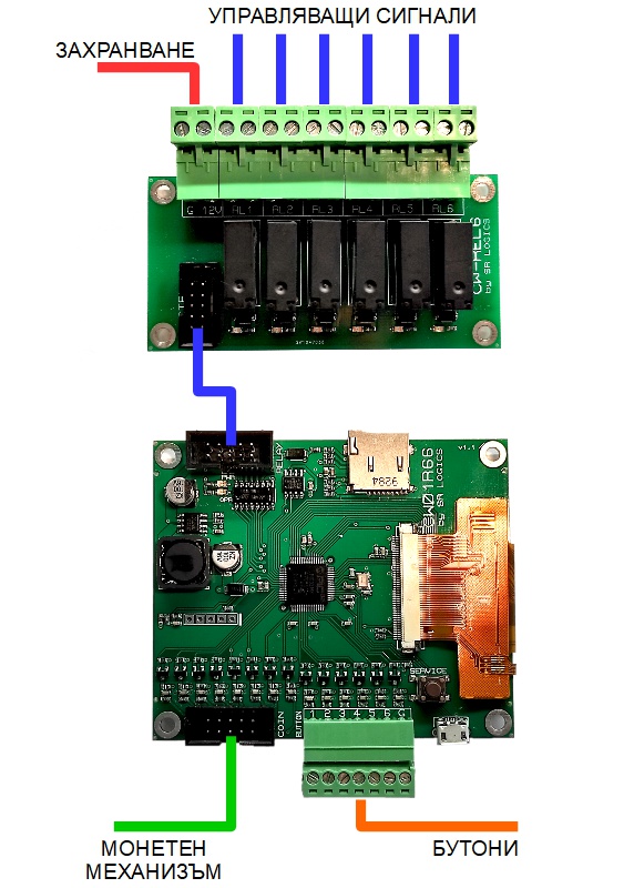
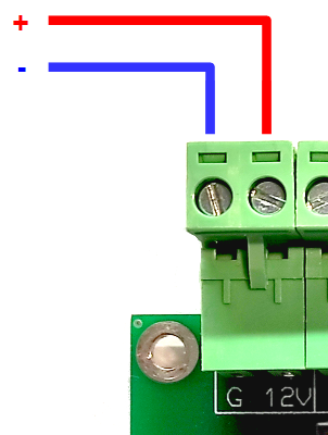
Power supply
The controller requires a power supply of 12V 0.5A. It provides the function of the display, the control relays, and the coin mechanism.
Control signals
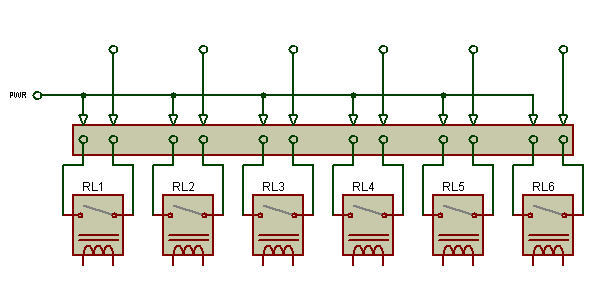
For control of the executive mechanisms such as pumps, valves, dispensers, and heaters are provided 6 relays as the contact circuit of each relay is shown on the labels. For each program could be made a random combination of active relays.
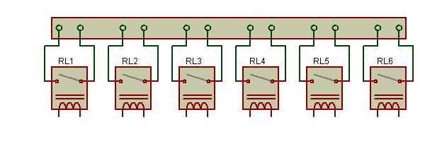 The maximum permissible load on each relay is 250V 5A.
Tip: To reduce the number of connected cables, power can be supplied to each pin and so when the free edge output is activated a control voltage will be directly available.
Coin mechanism
The communication with the coin mechanism is done over the standard parallel interface, using connectors with 2 x 5 pins. You can make a consultation with the documents of the coin mechanism to check if it matches the drawing.
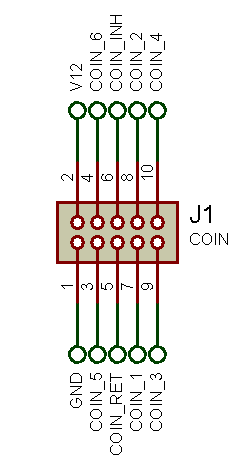
| outlet | name | description |
|---|---|---|
| 1 | GND | Common ground |
| 2 | V12 | Power supply 12V |
| 3 | COIN 5 | Impulse for a coin with code 5 |
| 4 | COIN 6 | Impulse for a coin with code 6 |
| 5 | RET | Returned coin / Impulse for a coin with code 7 |
| 6 | INH | Prohibition for acceptance of coin |
| 7 | COIN 1 | Impulse for a coin with code 1 |
| 8 | COIN 2 | Impulse for a coin with code 2 |
| 9 | COIN 3 | Impulse for a coin with code 3 |
| 10 | COIN 4 | Impulse for a coin with code 4 |
The controller is capable of recognizing the listed signals:
- single pulse for each of the 6 canals- this is how are maintained up to 6 different types of coins
- a sequence of pulses; for instance 1 pulse - 50 st., 2 pulse - 1 lev, 4 pulse - 2 levs
- pulses with different duration; for instance 100 ms. - 50 st., 200 ms. - 1 lev, 300 мс. - 2 levs
- a combination of codes (known as binary); for instance pulse simultaneously 1 and 2 canal- this is how are maintained more than 16 different coins
Buttons
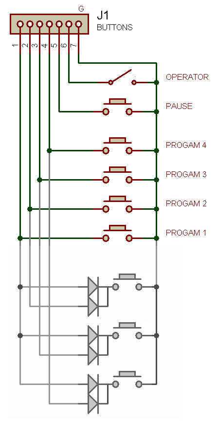
Свързването на бутоните се осъществява с шест сигнални линии и обща маса. Допуска се свързването на нормално отворени и нормално затворени бутони, както и ключове.
При необходимост от повече бутони, чрез използването на разделителни диоди е възможно един бутон да управлява няколко сигнални линии. По този начин е възможно свързването до 16 бутона за програми и ключ оператор.
Примерна пълна схема
Това е схема на изградена автомивка с 4 програми.
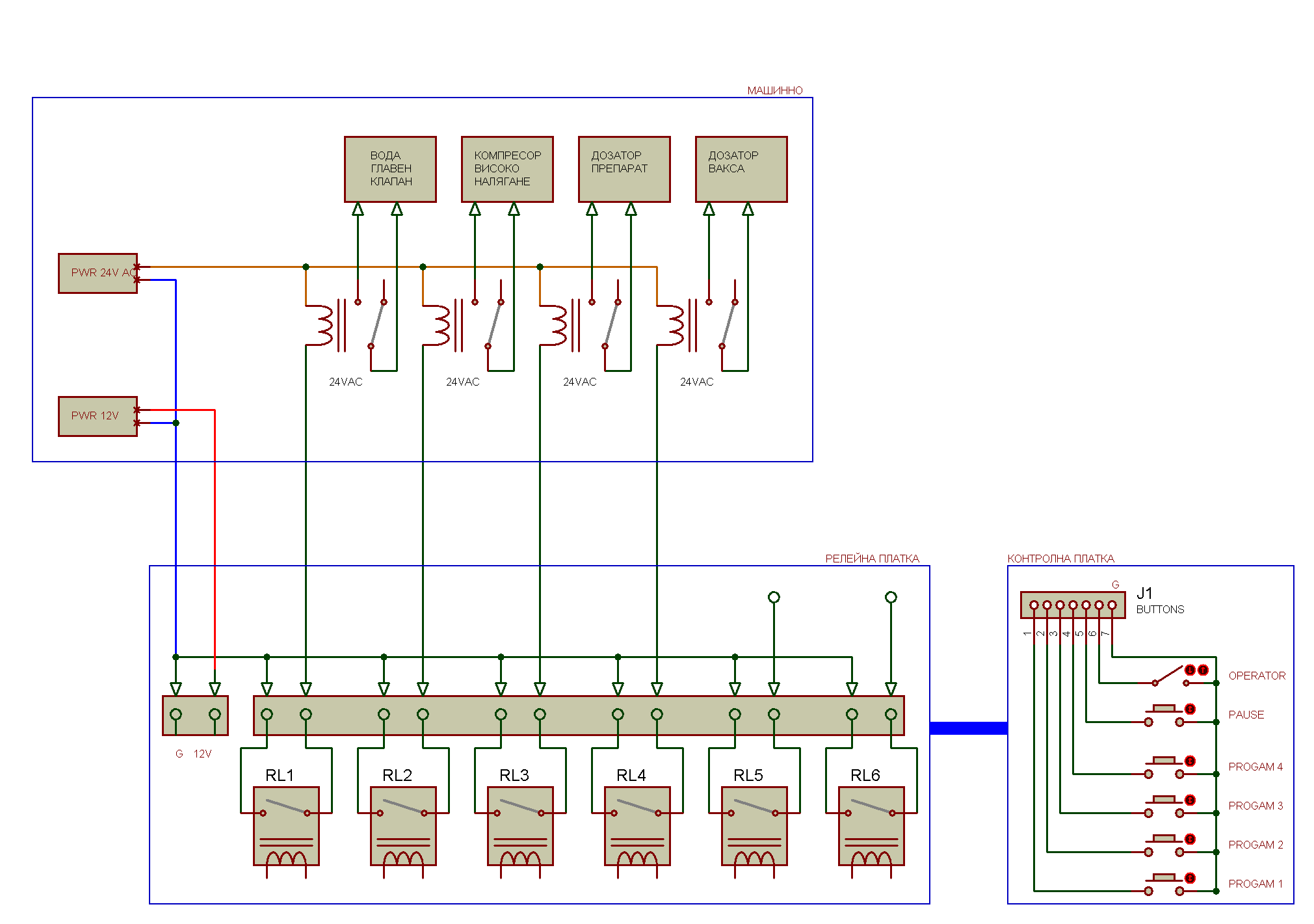 Използват се следните управляващи сигнали:
- Реле 1 - главен клапан за пускане на водата
- Реле 2 - компресор за високо налягане
- Реле 3 - дозатор да препарат
- Реле 4 - дозатор за вакса
За контролера е необходимо да се направят следните настройки на програмите:
| N | Програма | Изходи |
|---|---|---|
| 1 | Водоструйка | 1 + 2 |
| 2 | Препарат - ниско налягане | 1 + 3 |
| 3 | Препарат - високо налягане (пяна) | 1 + 2 + 3 |
| 4 | Вакса | 1 + 4 |